GET IN TOUCH
Reach out to our dedicated team at anytime
PHONE
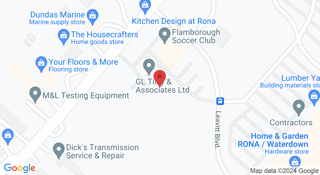
ADDRESS
46 Dundas St E, Dundas, ON L9H 7K6
GET IN TOUCH
Reach out to our dedicated team at anytime
PHONE
ADDRESS
46 Dundas St E, Dundas, ON L9H 7K6

Copyright 2023 G.L Tiley & Associates Ltd